Fenwal Ignition Module Wiring Diagram Hvac

Ad Ebay Fenwal Ignition Module Fits Lochinvar Rly2402 Next Day

741af Fenwal Ignition Module Wiring Diagram 35 630200 007 Wiring
Https Kidde Fenwal Com Media Installation 20instructions Ii 2035 608 20ce 06 237172 002 20ba Pdf

35 652505 003 Fenwal 35 652505 003 35 65 Series Ignition
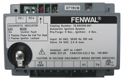
Fenwal Ignition Module Part 35 605500 001 Furnacepartsource Com

923cdf Fenwal Ignition Module Wiring Diagram Hvac Wiring Library
Fss cfd control unit p n 35003 38 ac dc 9 10 figure 6.
Fenwal ignition module wiring diagram hvac. Wiring diagrams 35 605 figure 1. Consult factory for longer lengths. Wiring diagram when connecting the 35 70 to other components in the system. Gas ignition control fenwal offers a complete range of ignition control including.
Consult factory for. High voltage spark cables and control wiring harnesses are detailed on pages 5 and 6. Smaller footprint wiring diagram high voltage and remote sense cable requirements the hv ignition cable must meet a voltage rating of 25 kv and an insulation rating of 200 c. I show you how to test for flame rectification to prove a pilot flame what the voltage readings should look like on the module what the sequence of operation is on the module and what to look.
Normal ignition should occur. Reset the system control module as described here. To reset the system adjust the temperature controller below room temperature wait 30 seconds and turn the temperature controller up to call for heat. The fenwal 35 608 series direct spark control 35 608 is a microprocessor based control suitable for many types of heat ing applications including hvac commercial cooking furnaces boilers and water heaters that require direct spark ignition burner supervision through flame rectification and safety shut off.
Fenwal instruction manual fenwal continuous fire and overheat detection system for industry fss publication 602 page iii 21 november 1996 list of illustrations and tables cont d page figure 4. Remote sense wiring diagrams 35 602 figure 3. Wiring diagrams 35 61 figure 1. If the control module goes into safety lockout it will remain locked out until the system is reset.
Ignition controls spark and flame sense electrodes. Remote sense high voltage and remote sense cable requirements the hv ignition cable must meet a voltage rating of 25 kv and an insulation rating of 200 c. The fenwal controls pim series 35 9x is designed for applications that require precise burner control high efficiency and enhanced performance. 05 33 without inducer wiring diagram figure 2b.
It is an integrated modular system control solution that combines gas ignition burner modulation temperature control hi limit and system functionality in a configurable scalable package that serves as the central wiring point for the appliance. Recommend length of 3ft 9m or less. The ignition module controls the ignition coil or the firing time of that coil to ensure the ongoing efficiency of any heating product. Local sense figure 2.
Local sense figure 2. Explosion proof enclosure 6 figure 5.
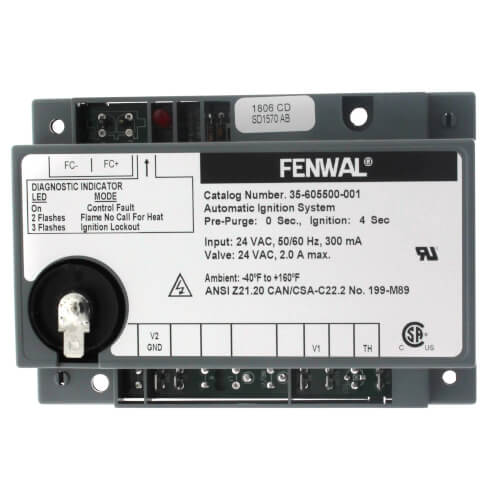
35 605500 001 Fenwal 35 605500 001 Direct Spark Ignition

Fenwal 35 535811 113 Installation Manual Manualzz

Mo 5520 Honeywell Ignition Module Wiring Diagram Free Diagram
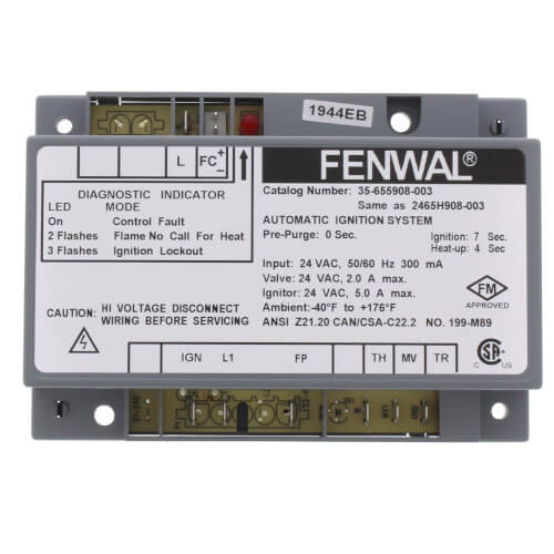
35 655908 003 Fenwal 35 655908 003 Hot Surface Ignition
35 605311 221 Fenwal 35 605311 221 Direct Spark Ignition
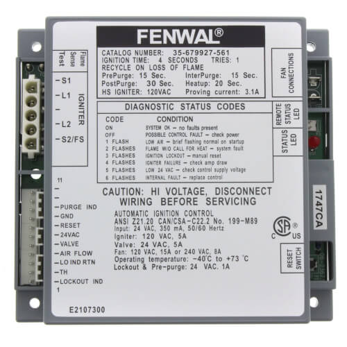
35 679927 561 Fenwal 35 679927 561 Hot Surface Ignition

Ad Ebay Tpi Dcs403 5100 Heater Accessory Disconnect Switch 3
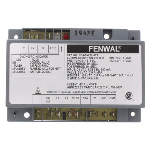
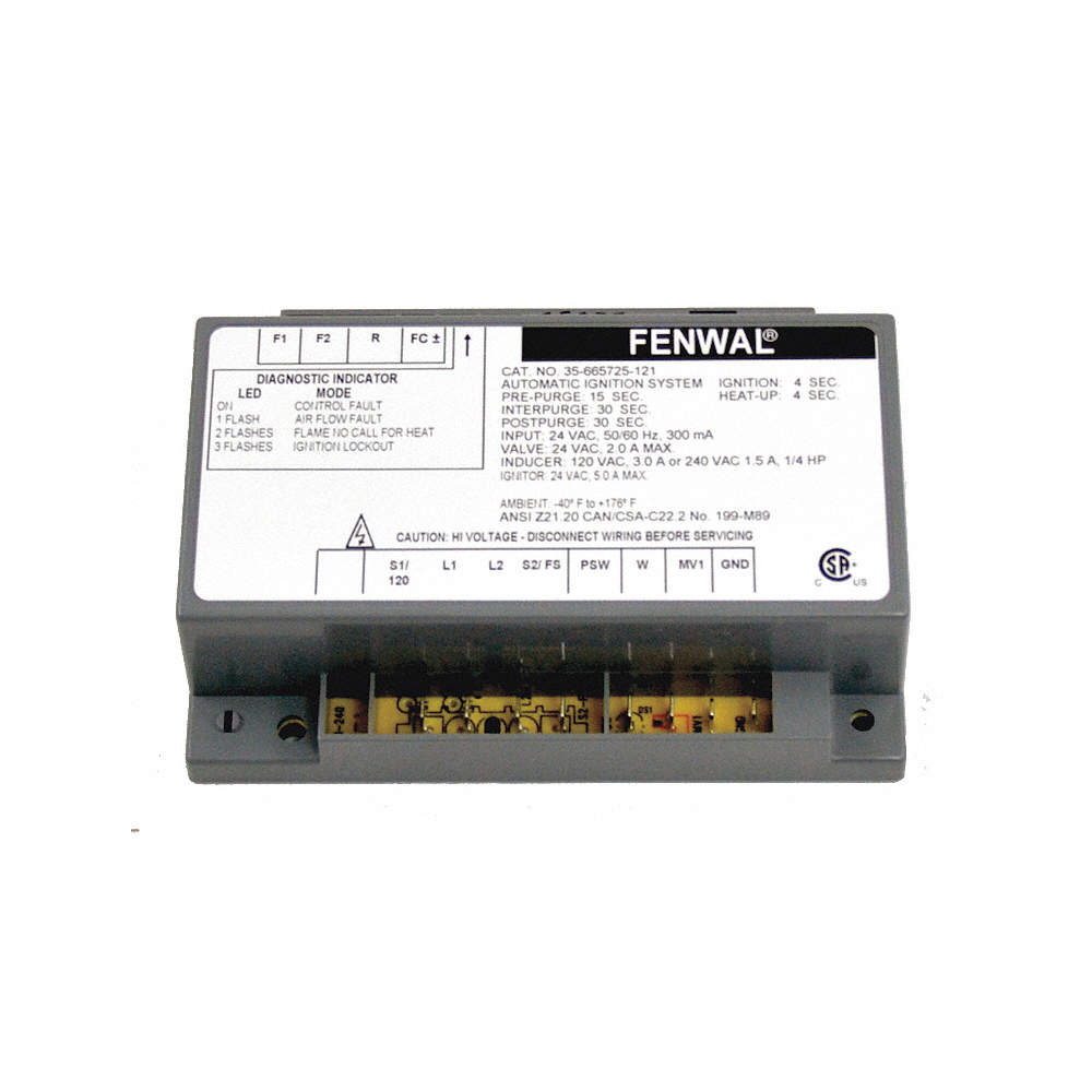
35 665725 121 Fenwal 35 665725 121 Hot Surface Ignition

Pin On Hydraulics Pneumatics And Pumps
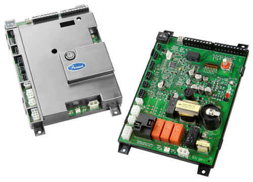
24vac Pim Gas Ignition Control Fenwal Controls
Fenwal Ignition Controls Control Board 24v Fits Brand Fenwal
35 615516 111 Fenwal 35 615516 111 Direct Spark Ignition

35 615926 203 Fenwal 35 615926 203 Direct Spark Ignition
