For Thermostat T8411r Wiring Diagram

Wire A Thermostat With Images Thermostat Wiring House Wiring

Unique Honeywell T6360b Room Thermostat Wiring Diagram Diagram

Nest Thermostat Wiring Diagram Thermostat Wiring Nest

How To Wire An Air Conditioner For Control 5 Wires Easy

Intertherm Thermostat Wiring Diagram Med Billeder

Thermostat Wiring Explained With Images Thermostat Wiring
09 10 2018 09 10 2018 6 comments on honeywell thermostat t8411r wiring diagram.
For thermostat t8411r wiring diagram. Setting fan and system switches t8411r electronic heat pump thermostat engage tabs at top of thermostat with slots on mounting plate. A 7 3 8 in. The tr heat pump thermostat provides 24v control of a two stage. Caution electrical shock or equipment damage hazard.
A letter code is located near each terminal for identification. Color of wire and termination. T8411r two stage heat and one stage cool wiring diagram with manual changeover. T8411r electronic heat pump thermostat refer to fig.
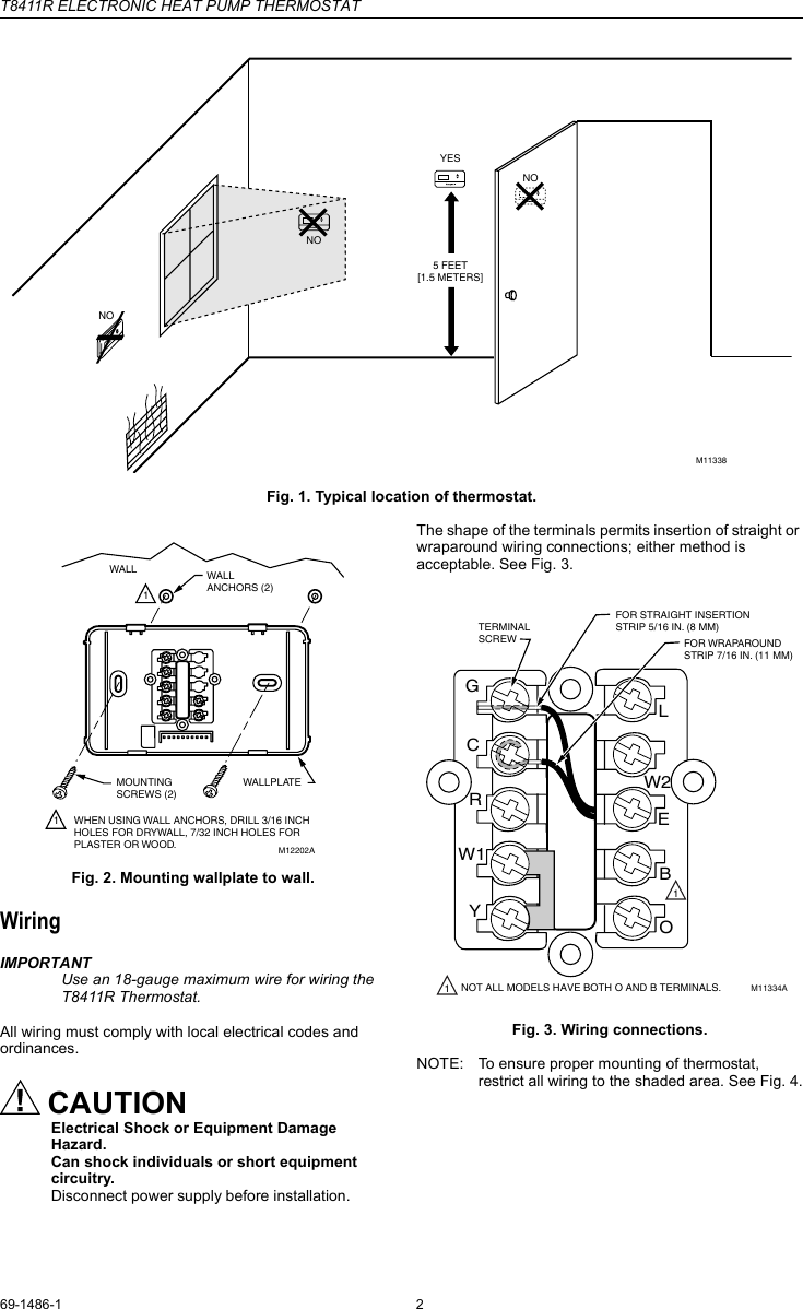
Wiring important use an 18 gauge maximum wire for wiring the t8411r thermostat. T8411r electronic heat pump thermostat 69 1481 1 2 fig. Tr two stage heat one stage cool wiring diagram with manual changeover. Setpoints are held permanently in memory and retained during power outages.
The t8411r heat pump thermostat is powered directly from the system transformer. It is a red wire and comes from the transformer usually located in the air handler for split systems but you may find the transformer in the condensing unit. R the r terminal is the power. 188 mm x 5 3 4 in.
Heating and one stage cooling heat pump system with manual. Typical location of thermostat. T8411r two stage heat and one stage cool wiring diagram with manual changeover. The t8411r includes a thermostat wallplate for wiring and mounting thermostat and owner s guide.
All wiring must comply with local electrical codes and ordinances. Mounting wallplate to wall. Restrict all wiring to the shaded area between the terminals. Thermostat wiring and wire color chart thermostat wiring colors code.
5 for typical wiring hookups.

New Bryant Gas Furnace Wiring Diagram Diagram Diagramsample

House Thermostat Wiring Diagram Thermostat Wiring Hvac

Wire A Thermostat Thermostat Wiring Honeywell Thermostats

Heat Pump Thermostat Wiring Chart Diagram Easy Step By Step

Carrier Hvac Thermostat Wiring Diagram Hvac Thermostat

Wiring Diagram Intertherm E2eb 012ha Goodman Entrancing Electric

Air Conditioner Thermostat Wiring Diagram Awesome Stunning Lennox

Unique Wiring Diagram Of Electric Cooker Diagram Diagramsample

Unique Simple Electrical Circuit Diagram Diagram Wiringdiagram

Siemens G120 Wiring Diagram On Images Free Download Inside With

Thermostat Wiring Diagrams Wire Installation Simple Guide

Split Ac Wiring Diagram Image With Images Ac Wiring

New Wiring Diagram Ice Maker Diagrams Digramssample
