For Twin Esc Wiring Diagram

Ba 9690 For Twin Esc Wiring Diagram Schematic Wiring

Esc Configurations Electrical Wiring Diagram Wire Boat Building

Pin On Diagram Formats

16 Rc Car Wiring Diagram Car Diagram In 2020 Rc Cars Car

Electric Bike Controller Wiring Diagram In Addition Electric Motor
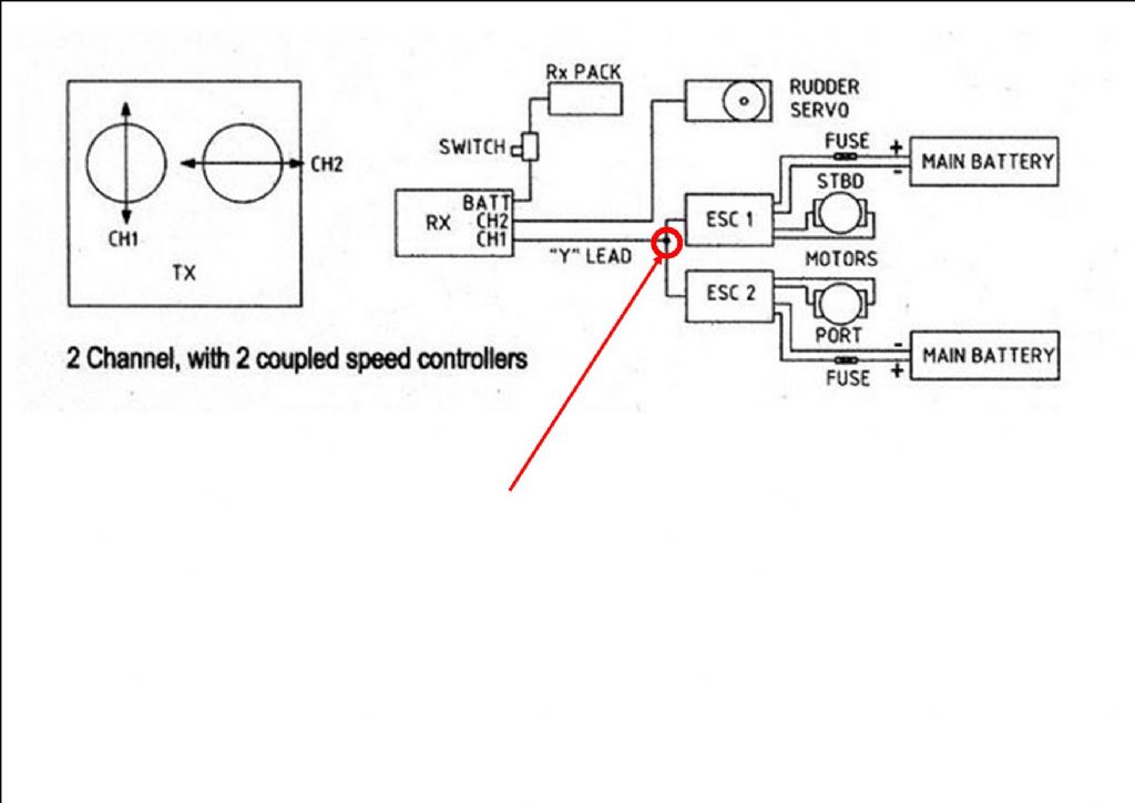
Twin Brushless Set Up Model Boats

3ø wiring diagrams 1ø wiring diagrams diagram er9 m 3 1 5 9 3 7 11 low speed high speed u1 v1 w1 w2 u2 v2 tk tk thermal overloads two speed star delta motor switch m 3 0 10v 20v 415v ac 4 20ma outp uts diagram ic2 m 1 240v ac 0 10v outp ut diagram ic3 m 1 0 10v 4 20ma 240v ac outp uts these diagrams are current at the time of publication.
For twin esc wiring diagram. How to wire dual esc s rchelpdotcom. Learn how to wire your multi engine electric rc aircraft. Kurt steps you through connecting your brushless motors to the escs the escs to the radio system and even touches on single or multiple. Here is the diagram when looking at the bottom of the skateboard.
The second thing to think about is easy access to the motor location or nacelles especially for esc placement which should have some type of airflow going through it. Differential throttle mix for twin motors on a 9x radio with er9x firmware duration. If using an opto esc then the centre wire should be left in place as it is needed for the esc to work. Rc boat twin brushed motor twin esc wiring diagram 07 11 2018 07 11 2018 3 comments on rc boat twin brushed motor twin esc wiring diagram very first boat having now got my twin motors each connected up to not easy to remotely diagnose your problem with rc system.
The term esc stands for electronic speed control is an electronic circuit used to change the speed of an electric motor its route and also to perform as a dynamic brake. These are frequently used on radio controlled models which are electrically powered with the change most frequently used for brushless motors providing an electronically produced 3 phase electric power low voltage source. It took me a while to figure out the wiring for the dual maytech 90mm sensored hub motors to the flier twin motor 120a esc so i decided to share my findings.

Universal Esc Circuit For Bldc And Alternator Motors With Images

Micro820 Plc Wiring Diagram With Images Diagram Electrical
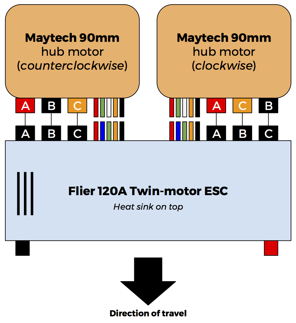
Wiring Maytech Hub Motors To Flier Twin Esc Electronics

Automobile Engine Parts Diagram Simple Guide About Wiring

Hobbyking Yep 7a 1 2s Brushless Speed Controller
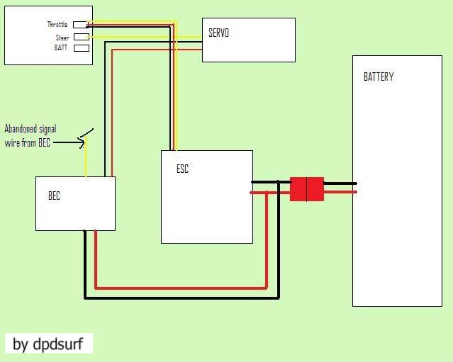
Definitive Wiring Diagrams For Becs Rx Servos Motors Etc Rccrawler

Number Of Poles And Magnets The 9 Pole Motor And The Reduction

Ny 4081 30 Amp Esc Wiring Diagram Wiring Diagram

F4 Racing Stm32f4 Cpu Flight Control Compatible With Librepilot

Traxxas Evx 2 Manual

Page 1 Of 49rx Rc Car Racing Car Schematics No Title Better

Sensorless Bldc Motor Control With Arduino Diy Esc

3 Phase Brushless Dc Motor 3 Phase Brushless Dc Motor Controller
